Electricity powers everything around us, from a mobile charger to giant industrial machines. Yet, many people find electrical terms confusing. This guide explains electricity simply and practically, using analogies, real-world examples, and clear transitions, so that even beginners can understand how power is generated, distributed, and used in homes and industries.
What Exactly Is Electricity?
Electricity is nothing but the flow of electrons through a conductor.
Consider it as water moving through a pipe. When electrons flow, electricity is created.
Electrons = water droplets ,Wire = water pipe ,Flow speed = current ,Pressure = voltage
This simple water analogy makes all electrical concepts clearer, with the difference that :
- Electrons flow from negative(-ve) to positive(+ve). Electrons are attracted to the positive terminal due to its negative charge.
- conventional current flow from positive(+ve) to negative(-ve).
Voltage & Current: The Most Important Relationship
- Voltage (V) is the force or pressure pushing electrons.
- Current (A) is the flow of electrons caused by that force.
A high voltage means a strong pushing force, while current indicates the amount of electricity actually moving through the wire.
AC vs DC — The Core Difference

| aC (Alternating current) | dC (Direct current) |
| AC keeps changing direction rapidly -50 times per second (50Hz in India) | DC flows in one fixed direction, just like water flowing in a straight channel. |
| ideal for: Long-distance transmission, Household appliances, Industrial equipment | Perfect for: Batteries, Mobiles, Laptops, LED lights, EVs |
| power source: power plants(Thermal, solar, hydro,nuclear,geothermal) wind turbine | power source: Batteries, solar panels, DC adapters, rectifiers |
| Voltage can be stepped up or down easily by transformers | DC offers a stable voltage, requiring converters for voltage conversion |
| Frequency 50-60 Hz | Frequency 0 Hz due to steady flow |
| aC can be converted to DC using rectifiers | DC can be converted to AC using inverters |
| excellent for long-distance transformation | high losses over long-distance transformation |
| more dangerous for humans & living things due to changing polarity | Comparatively safer at low voltage |

“That’s why chargers convert AC to DC before your phone receives power.”
Single Phase AC vs Three Phase AC

| Single Phase (Used in Homes – 215/230V) | Three Phase (Used in Industries – 415V) |
| 1 phase (one live wire + one neutral) | 3 phase (three live wires + one neutral optional) |
| Voltage level 230V-240V | Voltage level 400-415V(line to line),230V(line to neutral) |
| pulsating power delivery | Smooth & continuous power delivery |
| suitable for light loads | suitable for heavy loads |
| Single-pole MCB, RCCB, and stabilisers are used in the circuit | 3-pole/4-pole mCB, MCCB, Contactor, overload relays used in the circuit |
| low starting torque | high starting torque |
| less stable under load variations | very stable under heavy loads |
| used in shops, homes for fans, lights, TVs, small pumps & motors, refrigerators, etc | used in industries & commercial plants for elevators, compressors, heavy pumps & motors, CNC machines, Transformers & MCC panels, VFD controlled machinery, etc |
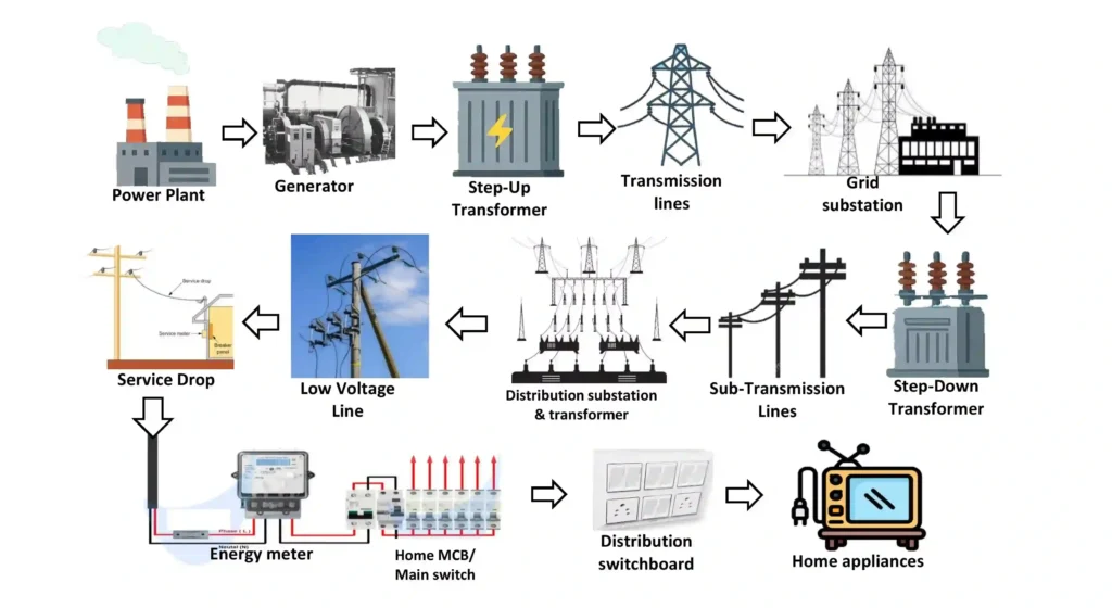
How Electricity Reaches Your Home or Industry
Electricity travels a long journey before it reaches your switchboard.
- Power Plant – Electricity is generated (usually 11 – 25 kV).
- Generator – Produces AC power.
- Step-Up Transformer – Voltage increased to 132/220/400 kV.
- Transmission Lines – Carry power over long distances.
- Grid Substation – Receives high voltage power.
- Step-Down Transformer – Voltage reduced (e.g., 400 kV to 132 kV).
- Sub-Transmission Lines – Carry power to local areas.
- Distribution Substation – Further voltage reduction.
- Distribution Transformer – Steps down to 415 V (3-phase) / 230 V (single-phase).
- Low Voltage Lines – Supply electricity to streets.
- Service Drop – Line from pole to house.
- Energy Meter – Measures electricity units.
- MCB / ELCB / Main Switch – Protection devices.
- Distribution Board – Splits the supply to circuits.
- Home Wiring – Internal wiring.
- Appliances – Electricity is finally used.
Why Electricity Flows Easily in Conductors
- Conductors: Have many free electrons, so electricity flows easily.
- Semiconductors: Have a limited number of free electrons; electricity flows only when energy is supplied.
- Insulators: Have tightly bound electrons, so electricity cannot flow through them.
In simple words:
- Conductors (silver, copper, aluminium) – easy flow
- Semiconductors (silicon, germanium) – controlled flow
- Insulators (plastic, rubber, glass) – no flow
Basic Electrical Formulas
Ohm’s law is considered a fundamental principle for understanding basic electrical circuits. It states that the electric current through a conductor between two points is directly proportional to the voltage across the two points. The constant of proportionality is called the resistance.

Power Formulas in DC Circuits
- P = V x I
- P = I2 x R
- P = V2 / R
Power Formulas in Single-Phase AC Circuits
- P = V x I x Cos Ф
- P = I2 x R x Cos Ф
- P = V2 / R (Cos Ф)
Power Formulas in Three-Phase AC Circuits
- P = √3 x VL x IL x Cos Ф
- P = 3 x VPh x IPh x Cos Ф
- P = 3 x I2 x R x Cos Ф
- P = 3 (V2 / R) x Cos Ф
Where:
- P = Power in Watts
- V = Voltage in Volts
- I = Current in Amperes
- R = Resistance in Ohms (Ω)
- Cos Ф = Power Factor.

Power factor(Cos Ф) is a measure of electrical efficiency in AC circuits, representing the ratio of real power (kW, useful work done) to apparent power (kVA, total power drawn), and ranges from 0 to 1. A higher power factor (closer to 1) means more efficient power use.
Where AC, DC, Single-Phase & Three-Phase Are Used Together
| Supply Type | Voltage | Used In | Examples |
| AC – Single Phase | 230V | Homes | Lights, fans, ACs |
| AC – Three Phase | 415V | Industries | Motors, pumps, compressors |
| DC – Low Voltage | 5V–48V | Electronics | Phones, LEDs, laptops |
| DC – High Voltage | 300–800V | EVs, solar systems | Batteries, inverters |
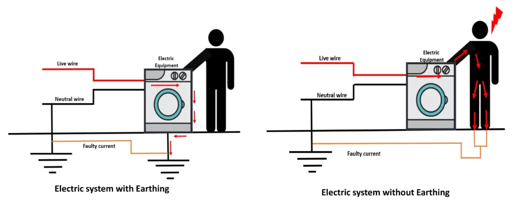
What is earthing?
It is the process of an instant discharge of electrical energy into the earth through a low-resistance wire & provides a safe path for leakage or fault current to flow into the ground. This prevents electric shock and protects both humans and equipment.
types of earthing(Physical installation types)
- Pipe Earthing: Most efficient & commonly used in homes and buildings; economical and effective in normal soil conditions.
- Plate Earthing: Used where soil resistivity is high; suitable for commercial and industrial installations.
- Rod Earthing: Used in rocky or hard soil areas; easy to install and requires less space.
- Strip / Wire Earthing: Common in substations and large electrical installations for grounding structures.
types of earthing(Functional types)
- Neutral Earthing
- Neutral earthing means connecting the neutral point of a power system (transformer or generator) directly to the earth.
- It is mainly done to stabilise system voltage and control fault current.
- Neutral earthing helps protective devices detect earth faults quickly.
- Commonly used in power stations, substations, and distribution transformers.
2. Equipment Earthing
- Equipment earthing means connecting the metal body of electrical equipment to the earth.
- Its main purpose is human safety during insulation failure or leakage current.
- It ensures fault current flows to the ground instead of through a person.
- Used in home appliances, industrial machines, panels, motors, and enclosures.
Note: Neutral earthing can be called grounding in power systems, but grounding does not always mean neutral earthing.
Importance of Earthing
- Protects people from electric shock.
- Ensures the quick operation of MCB and RCCB during faults.
- Reduces risk of electrical fire and equipment damage.
- Maintains voltage stability in electrical systems.
- Protects appliances from lightning and surge effects.
Earthing is achieved by connecting the neutral or non-current-carrying part of the equipment to ground.
Electricity can feel complicated, but when broken into simple ideas, it becomes easier than expected. With practical analogies, everyday examples, and basic formulas, anyone can understand how electricity works in homes, industries, and machines.
Click to understand the difference between earthing & grounding.
Read about Basic Mechanical Components and Their Functions