In an internal combustion vehicle, the starting system, charging system, and ignition system together form the core of the automobile electrical system. These three systems work together to provide electrical energy, convert it to mechanical power, and keep everything running efficiently. These systems ensures proper combustion control in spark-ignition (petrol) & compression-ignition(diesel) engines.
Modern vehicles, whether two-wheelers, passenger cars, commercial vehicles, or heavy-duty diesel machines, all rely on the same fundamental electrical principles such as Ohm’s law, electromagnetic induction, transformer action, and power balance, though the design and complexity may vary.
Overview – How These Systems Fit Together
| System | Purpose |
| Starting System | Turns the engine over (cranks) to start combustion |
| Charging System | Generates electrical power while engine runs and keeps battery charged |
| Ignition process | The ignition system needs stable voltage and timing information to create combustion. 1)spark-ignition(petrol) – spark plug produce high voltage spark to ignite the air-fuel mixture . 2)compression-ignition(Diesel)- fuel self-ignites when injected into highly compressed air. |
A weak battery affects all three – slow cranking, poor spark and undercharging can cascade
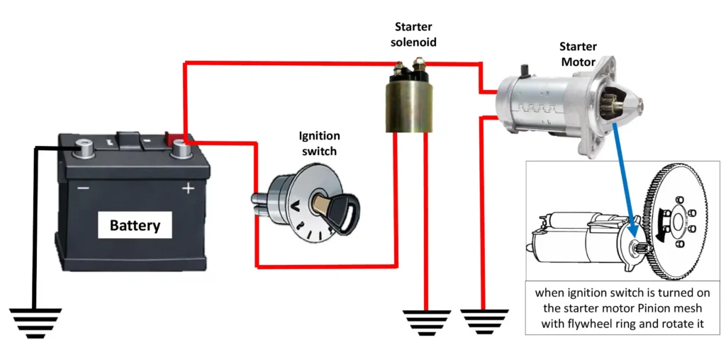
1. Starting System – Working & Components
The starting system provides the initial mechanical force needed to turn the engine’s crankshaft until the engine runs under its own power or engine can start combustion on its own.
Key Components
- Battery (12V Lead-acid) – supplies stored electrical energy to power the starter and ignition systems.
- Ignition Switch / Start Button – when activated, connects the battery to the starter circuit & Sends start signal to solenoid.
- Starter relay/Solenoid – electromagnetic switch that Engages starter motor and completes high-current circuit.
- Starter Motor(DC series motor) – it Converts electrical energy into mechanical torque to rotate the armature , which drives the engaged starter gear meshed with flywheel(Ring gear).
- Drive Mechanism (Bendix Gear) – engages starter gear with flywheel teeth.
Working steps of Starting System (Battery-Starter Motor)
1. Battery supplies high current
- The battery (12 V lead-acid) supplies DC electrical energy.
- Voltage is low (12 V) but current is VERY HIGH (hundreds of amps).
- This current is needed to rotate the engine.
2. Ignition switch / start button is turned oN
When the key is turned or start button pressed :
- A low-current control circuit is completed & Battery power is sent to the starter relay / solenoid coil
3. Starter solenoid is energized :The starter solenoid is an electromagnetic switch.
When current flows through solenoid coil:
- A strong magnetic field is created & A plunger inside the solenoid moves forward
4. Starter pinion gear engages flywheel
As the solenoid plunger moves:
- It pushes the starter drive (Bendix gear) forward
- Starter pinion gear meshes with flywheel ring gear teeth
Gear engagement happens Before motor starts rotating (to prevent gear damage).
5. High-current circuit is completed At full solenoid travel:
- Heavy copper contacts inside solenoid close
- Battery positive is directly connected to starter motor(full battery current flows to starter motor)
6. Starter motor converts electrical energy into torque
Starter motor is a DC series motor, When high current flows:
- Strong magnetic field is created in field windings
- Armature starts rotating with very high torque
(Starter motor torque is much higher than normal electric motors)
7. Flywheel and crankshaft rotate
- The rotating starter pinion gear turns Flywheel & Flywheel turns crankshaft
Engine starts cranking (intake, compression, combustion cycles begin).
8. Engine starts combustion As crankshaft rotates:
- Ignition system produces spark & Fuel system supplies fuel
9. ignition Key released – starter disengages
When key is released from START to ON position:
- Solenoid coil is de-energized
- Return spring pulls pinion gear back & High-current circuit opens
Starter motor stops and disengages safely.
Battery → Ignition switch → Solenoid energizes → Pinion engages flywheel → High current flows → Starter motor rotates → crankshaft turns → Engine starts
*notes
- the starter solenoid creates a magnetic pull that moves the starter gear forward via a shift lever, allowing it to mesh with the flywheel before torque is applied.
- Turning the key or pressing the start button just closes the circuit.
- Starter motor spins the flywheel, cranking the engine until it starts.
Starting System Behavior Under Different Conditions
- Diesel engines require higher cranking torque due to higher compression.
- Cold weather increases battery internal resistance, causing slow cranking.
- Poor grounding or corroded terminals can cause starting failure even with a good battery.
- Frequent short trips prevent full battery recharge, leading to weak starting.
Common Starting System Faults symptoms & cause
when start switch turned ‘ON’ –
| Symptom | System condition | Probable Cause |
| No response | Zero voltage & current | Dead battery, faulty switch |
| Clicking sound | Not enough current | Weak battery or loose terminals |
| Engine not cranking | No power to starter motor | Starter solenoid failure |
| improper/poor cranking | Reduced starter motor performance | Worn brushes & armature |
| Slow cranking | Not enough current | Battery ageing, starter wear |
| intermittent/hard starting | Voltage drop in circuit | Loose cabling or corroded terminals |
| Grinding noise | moving parts wear sound | Worn pinion or flywheel teeth |
2. Charging System – Working & Components
The charging system supplies electrical power to all vehicle loads during engine operation and recharges the battery after starting. Without a charging system, the vehicle would stop once the battery is discharged.
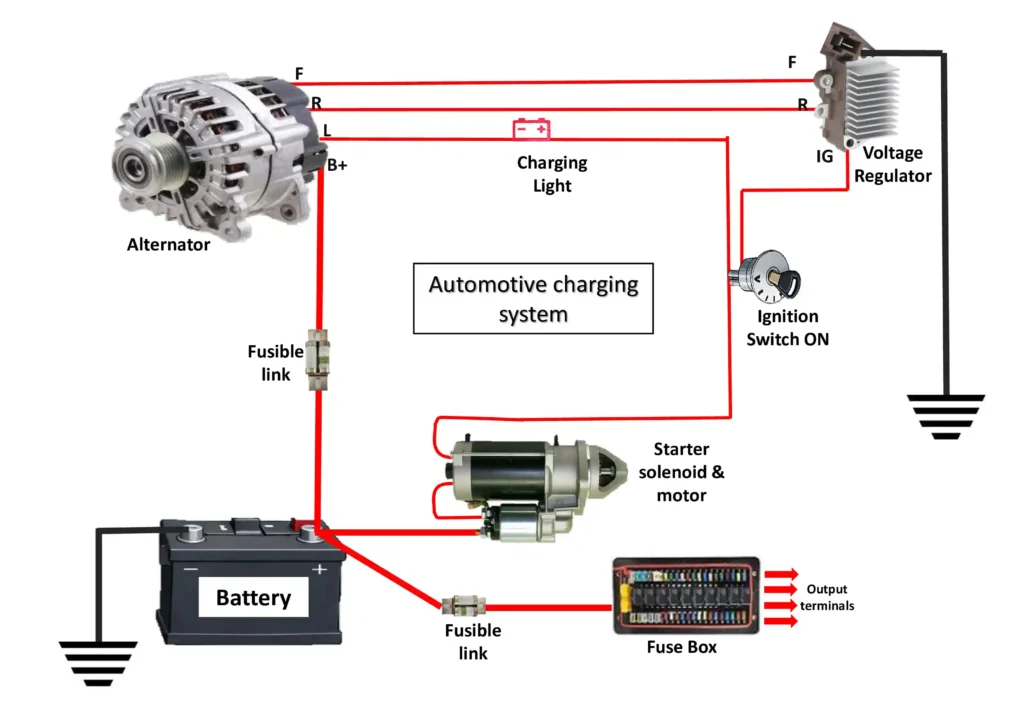
Key Components
- Alternator (AC Generator) – engine-driven device that produces electrical power.
- Rotor Creates rotating magnetic field & Stator Produces AC voltage
- Rectifier (Diode Bridge) – Converts AC to DC (Diode bridge = mostly 6 diodes , 2 diodes for each phase)
- Voltage Regulator – controls alternator output voltage to keep stable (around 13.8 – 14.5 V).
- Battery – Stores energy & stabilizes voltage, provides starting energy.
- Drive Belt (Serpentine/V belt) – spins the alternator pulley & Transfers engine rotation to alternator
Working steps for Charging System (Alternator-Based)
1. Engine rotation drives alternator Once engine is running:
- Crankshaft rotates
- Drive belt (V-belt / serpentine belt) spins alternator pulley
Alternator works only when engine is running.
2. Rotor receives field current
- Battery supplies a small DC current to alternator rotor through Slip rings & Brushes (or internal electronic control)
(Rotor = rotating electromagnet inside alternator)
3. Rotor creates rotating magnetic field When current flows in rotor winding:
- Rotor becomes an electromagnet
- As rotor spins, its magnetic field also rotates
Magnetic field rotation is essential for power generation.
4. AC voltage is induced in stator windings
The stator is fixed and has three-phase windings.
- As rotating magnetic field cuts stator windings:
- AC voltage is induced (electromagnetic induction)
Alternator produces AC power, not DC.
5. Rectifier converts AC to DC Vehicle electrical system needs DC power.
- Rectifier (diode bridge) converts AC to DC
- Usually consists of 6 diodes (2 diode per phase)
Diodes allow current in one direction only.
6. Voltage regulator controls output voltage The voltage regulator monitors system voltage.
- If voltage is LOW → regulator increases rotor field current.
- If voltage is HIGH → regulator reduces rotor field current
Output voltage is maintained around 13.8V – 14.5 V.
7. Electrical loads are supplied
The regulated DC power supplies to:
• Lights • ECU • Sensors • Fans • other Accessories
Alternator supplies all electrical loads during engine running.
8. Battery is recharged After supplying vehicle loads:
- Excess current flows to battery
- Battery is recharged and stabilized
Battery acts as a voltage stabilizer and energy backup.
9. System balances automatically As engine speed and load change:
- Alternator output changes.
- Regulator adjusts field current instantly.
Charging system is self-regulating.
Engine rotation → Alternator rotor spins → Magnetic field cuts stator → AC generated → Rectifier converts AC to DC → Regulator controls voltage → Loads supplied + Battery charged
*notes
- DC Charging voltage ≈ Alternator output – (Voltage drop in wiring)
- charging occur when : alternator voltage > battery voltage
- If battery voltage < Alternator set point → regulator increases field current → more output.
- If battery voltage > Limit → regulator decreases output.
- Rectifier is the diode assembly located inside the alterntor that converts ac output to dc for charging battery.
Common charging System Faults symptoms & cause
| Symptom | System Condition | Probable Cause |
| Battery Not Charging | Zero / low charging voltage | Broken or loose alternator belt, faulty alternator |
| Battery Discharges While Driving | Charging stops intermittently | Slipping belt, loose wiring |
| Battery Overcharging | Excessive voltage | Faulty voltage regulator |
| Battery Undercharging | Low voltage output | Weak regulator, worn carbon brushes of alternator |
| Battery Drains Overnight | AC ripple / leakage | Rectifier diode failure |
| Flickering / Dim Lights | Unstable voltage | Loose electrical connections, regulator issue |
| Charging Warning Lamp ON | No alternator output | alternator Belt failure, alternator fault |
| Charging Lamp Flickers | Intermittent charging | Loose belt or wiring |
| Electrical Noise / Whine | AC ripple in DC | Rectifier Diode failure in alternator |
| Battery Boiling / Heating | Excess current | Regulator overcharging |
| Alternator Overheats | Internal short | Shorted diode or winding |
| Burning Smell | Electrical overload | Alternator internal fault |
| Good Alternator, No Charge | Open charging circuit | Corroded electrical terminals, poor grounding |
| Voltage Fluctuates with RPM | Regulation unstable | Faulty voltage regulator |
| Grinding / Whining Noise | Mechanical failure | Alternator bearing wear |
| Battery Won’t Hold Charge | Internal battery fault | battery aging/sulfation |
3. Ignition System – Working & Components
The ignition system produces a high-voltage spark at precisely the right time to ignite the compressed fuel-air mixture in gasoline engines. Without this spark, combustion won’t start and the engine cannot run.
Key Components
- Battery – supplies low-voltage power(E.G 12V/24V) to starter motor.
- Ignition Switch/start button- Low-current signal flows from battery to starter solenoid. Starter solenoid energized ,Solenoid creates a magnetic field.
- Ignition Coil – steps up battery voltage to high voltage (up to tens of kV).
- Distributor (older vehicles) – routes high voltage to correct spark plug.
- Spark Plug & Injector – spark plug produce spark in SI Engine or injector injects fuel in cI Engine cylinder.
- Control Module / ECU – modern timing control.
- Wiring, Sensors (crank/cam position sensors) – help timing and precision.
Working steps for ignition system
1. Battery supplies low voltage
- The battery (12 V) supplies low-voltage DC current.
- This current flows toward the ignition coil primary circuit.
At this stage, voltage is LOW and safe.
2. Current flows through ignition coil primary winding
- The ignition coil has:
- Primary winding (few turns, thick wire)
- Secondary winding (many turns, thin wire)
- A soft iron core inside the coil
“Core” = soft iron core inside the ignition coil, not engine metal.
3. Magnetic field builds around the iron core
- When low-voltage current flows through the primary winding, it creates a magnetic field.
- This magnetic field builds up around the iron core of the ignition coil.
Think of the ignition coil as an electromagnet at this moment.
4. ECU / ignition module interrupts the primary current
- At the correct engine timing (using crank/cam sensor signals),
- The ECU or ignition module suddenly cuts OFF the primary current.
This timing is critical (just before piston reaches TDC).
5. Magnetic field collapses rapidly
- When current stops suddenly:
- The magnetic field around the iron core collapses very fast.
(Rapid collapse is the key — slow collapse = weak spark)
6. High voltage is induced in secondary winding
- Due to electromagnetic induction:
- The collapsing magnetic field induces very high voltage in the secondary winding.
- because the secondary winding has thousands of turns so Voltage increases to 20,000–40,000 volts.
This is why the ignition coil is often called a step-up transformer.
7. High voltage travels to the spark plug
- The high-voltage output from the secondary winding:
- Goes through HT lead / coil-on-plug
- Reaches the spark plug.
8. Spark jumps across spark plug gap
- The high voltage overcomes air resistance in the spark plug gap.
- A spark jumps between center electrode and ground electrode.
Spark = very hot electric arc.
9. Air–fuel mixture ignites
- The spark ignites the compressed air-fuel mixture.
- This happens just before piston reaches Top Dead Center (TDC).
Combustion pushes piston downward → engine power.
Battery → Primary winding → Magnetic field builds (coil core)→ ECU cuts current → Magnetic field collapses → High voltage induced → Spark plug fires → Combustion
Types of Ignition Systems
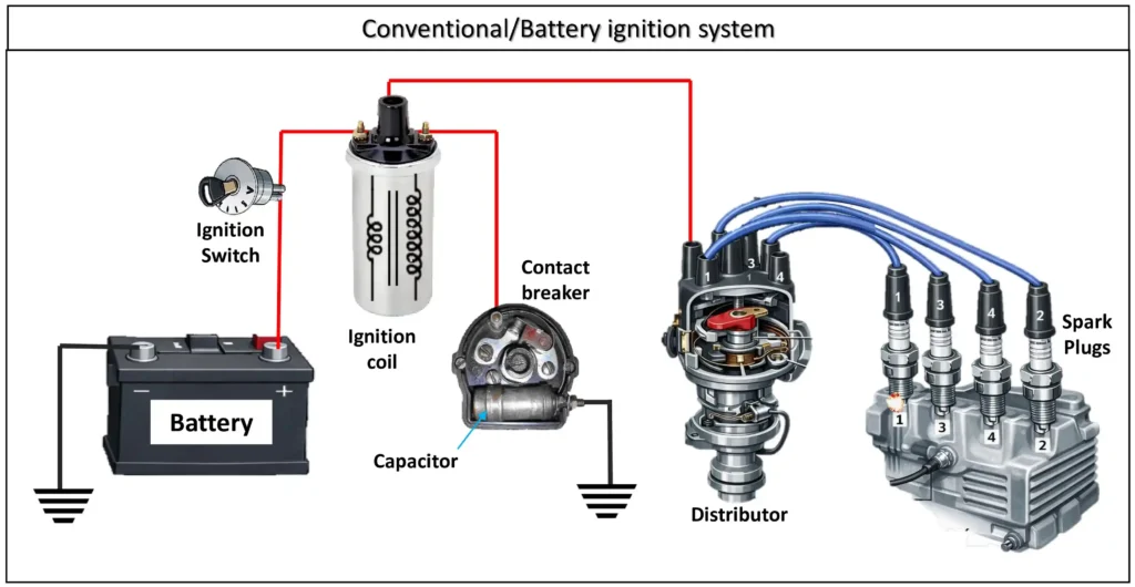
- Conventional (Breaker Point) Ignition System: Uses contact breaker points ,Requires regular adjustment,Simple construction & Spark quality decreases with wear.
- Mechanical distributor type
- Ballast resistor type
Used in Older cars (pre-1980s),Some old motorcycles.
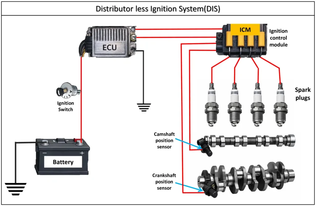
2. Distributor-less Ignition System (DIS) : No mechanical distributor, Controlled by ECU, More reliable and precise timing, Better fuel efficiency & low emission
- Wasted Spark System (Coil pack for 2 cylinders)
- Direct Ignition
- Coil-On-Plug (COP)
Used in Modern petrol cars , EFI engines
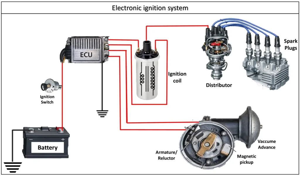
3. Electronic Ignition System (Modern Standard) : Uses transistors instead of breaker points,More accurate spark timing,Low maintenance , Needs battery (except some AC-CDI)
- TCI (Transistor Controlled Ignition) type – Modern cars
- CDI (Capacitor Discharge Ignition) type – Motorcycles, scooters, racing engines
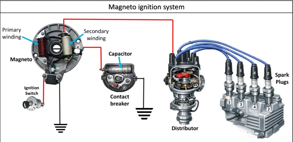
4. Magneto Ignition System : No battery required ,Generates own electricity, Reliable for independent operation, Not common in modern cars,
- Rotating armature type
- Rotating magnet type
Used in Small engines (lawn mowers, chainsaws),Kick-start motorcycles, Aircraft piston engines.
5. Compression Ignition (Diesel) : No spark plug, Fuel ignites by high compression, Uses glow plugs for cold start, Higher efficiency & torque ,
- Mechanical injection diesel
- Common rail diesel injection (CRDI)
Used in Diesel engine eg. diesel cars, trucks, tractors
Common ignition System Faults symptoms & cause
| Symptom | ignition Condition | Probable cause |
| No Spark (Engine Cranks) | Ignition totally inoperative | Dead battery, blown fuse, ignition switch failure |
| No Spark at All Cylinders | Primary circuit failure | Ignition coil / coil pack failure, ignition module fault |
| No Spark at One Cylinder | Secondary circuit failure | Faulty spark plug, plug wire, coil-on-plug |
| Weak / Yellow Spark | Low ignition energy | Worn plugs, wide plug gap, weak coil |
| Intermittent Spark | Unstable ignition signal | Loose wiring, poor grounding |
| Engine Cranks but No Start | Spark missing or mistimed | Crankshaft position sensor failure |
| Engine Starts then Stalls | Ignition signal lost after start | Cam sensor or ignition module fault |
| Hard Starting (Cold / Hot) | Weak spark under load or heat | Coil breakdown, heat-sensitive module |
| Engine Misfire (Single / Multiple) | Inconsistent ignition | Fouled plugs, weak coil, module fault |
| Rough Idle / Hesitation | Spark irregular under load | Dirty plugs, cracked HT leads |
| Poor Acceleration / Power Loss | Late or weak ignition | Incorrect timing, weak coil |
| Backfire (Intake / Exhaust) | Spark timing incorrect | Wrong firing order, timing error |
| Engine Knocking / Pinging | Spark too advanced | Incorrect timing, faulty knock sensor |
| High Fuel Consumption | Incomplete combustion | Weak spark, retarded timing |
| Engine Overheating | Late combustion | Retarded ignition timing |
| Sudden Engine Cut-Off | Ignition power loss | Ignition switch or sensor failure |
| Spark Present but No Start | Spark at wrong time | Incorrect ignition timing, timing belt slip |
| Check Engine Light ON | ECU detects misfire | Ignition coil, CKP/CMP sensor fault |
in Distributor Type (Older Engines)
| symptom | probable cause |
| Weak or No Spark | Burnt distributor cap, rotor damage |
| Erratic Timing / Jerking | Worn shaft, worn contact points |
| Spark Missing on Some Cylinders | Rotor misalignment, cap tracking |
Electronic Ignition (Modern Engines)
| symptom | probable cause |
| no RPM Signal | Crank sensor failure |
| Random Misfire Codes | Ignition module or coil pack |
| Engine Shuts Off Suddenly | Sensor signal loss to ECU |
| Coil Overheating | Internal short or excess current |
Most ignition faults are caused by weak spark, incorrect timing, sensor failure, or poor electrical connections.
General Faults & Diagnosis Logic
Starting System Clues
- Nothing happens, no click → battery dead / ignition switch/wiring.
- Clicks but doesn’t crank → weak battery or bad solenoid.
- Grinds/cranks slowly → starter gear issues.
Charging System Clues
- Battery warning light lit (dashboard) → charging problem.
- Dimming lights at idle → alternator undercharging.
- Overvoltage / boiling battery → regulator fault.
- Squealing belt noise → belt slipping.
Ignition System Clues
- Engine misfires / rough idle → bad plugs or coil.
- Hard start / no spark at plugs → ignition control or sensor fault.
- Engine stalling when warm → timing or module issues.
Formulas and Electrical Principles
| Concept | Approx value/Rule | Used in |
| battery full voltage | ~12.6 V | Starting |
| Minimum cranking voltage | not below 9.6 V | Starting |
| starter current draw | 100-300+ a | Starting |
| charging voltage | 13.8V – 14.5V | charging |
| alternator output | 40-120+ a | charging |
| ignition coil primary | 12 V | ignition |
| ignition coil secondary | 15000 -40000 V | ignition |
| spark plug gap | 0.6-1.1mm | ignition |
| Ohm’s law | V = I X R | all system |
| voltage drop rule | Should be <0.5V in cables | all system |
Voltage Drop Rule: If wiring or connectors are corroded,
then, voltage at component < battery terminal voltage → component misbehaves.
read more about how Automobile Electrical components work